
Shell & Plate Engineering Technology
Plate and channel design, welded flow boundaries, distribution, thermal and hydraulic selection, and mechanical engineering.
How shell & plate heat exchange works
Two separate fluid circuits exchange heat through corrugated metal plates. The plate pack establishes the flow boundaries; the surrounding pressure shell contains the assembly. Engineering selection brings together heat transfer, flow distribution and mechanical integrity.
Plate geometry & channel design
Corrugation and velocity
Corrugation angle, depth and channel gap influence mixing, contact points and flow resistance. Channel velocity must support heat transfer without exceeding the available pressure drop.
Fouling and hydraulic balance
A narrower channel can increase velocity, but also raises resistance and sensitivity to particles. Fluid viscosity, deposits and the cleaning strategy are reviewed together with surface area.
Welded plate-pack technology
Separate flow boundaries
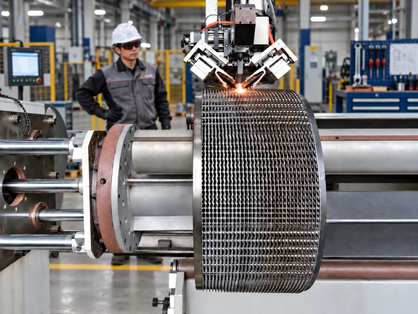
Circular plates are joined in pairs at their ports; adjacent pairs are joined around the perimeter. The welded boundaries separate plate-side channels from shell-side passages without interplate gaskets.
Channel integrity
Weld layout and plate support must accommodate pressure differences and temperature changes. Shell-cover sealing is a separate design choice and depends on the mechanical configuration.
Flow distribution
Loading the channels
Ports, shell-side passages and flow directors guide the inlet stream through the available surface. Unequal channel loading can leave part of the area underused and increase local pressure loss.
Distribution during phase change
Vapour volume, liquid feed, drainage and orientation are reviewed for condensing or boiling duty. Distribution and outlet routing must limit stagnant zones and unwanted liquid accumulation.
Thermal & hydraulic design
Temperature programme
Heat duty follows flow rate and enthalpy change. Counter-current arrangements can support a close temperature approach; the actual flow scheme determines the effective temperature driving force and LMTD correction.
Area versus pressure drop
Surface area, overall heat-transfer coefficient and temperature difference are balanced with channel velocity and allowable pressure drop. Fouling allowance, thermal margin and part-load conditions are considered during selection.
Two-phase technology
Condensation
Selection includes sensible cooling and latent heat removal. Vapour pressure loss, condensate drainage and non-condensable gases affect the usable temperature difference and surface performance.
Evaporation and boiling
Vapour quality changes along the flow path. Liquid supply, circulation, phase separation and pressure-drop behaviour must be reviewed to maintain wetting and stable operation across the required load range.
Mechanical design
Pressure containment
The cylindrical shell contains the assembly. Shell, cover, flanges and nozzles are assessed for the specified pressure, temperature, external loads and applicable project design requirements.
Expansion and cyclic duty
The pack and shell may heat at different rates. Differential expansion, repeated starts, thermal cycles and nozzle loads are reviewed when defining supports, connections and fatigue requirements.
Welding engineering
Seam design and heat input
Seam position, penetration and heat input must form a continuous flow boundary while controlling the heat-affected zone and distortion of thin plates. The joining method depends on material and joint geometry.
Repeatability and integrity
Consistent fit-up and process control support repeatable joints. Material compatibility and the agreed inspection scope are part of weld qualification and channel-integrity review.
Plate heat transfer: from geometry to duty
Developed surface and boundary layers
Corrugations increase the developed surface beyond the projected circular area and repeatedly redirect the fluid. Mixing disrupts thermal boundary layers, but its benefit must be balanced against friction and pumping energy. Heat-transfer correlations depend on the actual plate geometry and fluid properties; a correlation from another plate family cannot be used as a rating guarantee.
What determines the overall coefficient
Q = U × A × F × ΔTlm
The overall coefficient combines resistance on both fluid sides, conduction through the plate and deposits on each surface. Area cannot compensate for an unsuitable flow distribution or an unrealistic fouling allowance. The LMTD correction follows the real pass arrangement; counter-current and co-current layouts produce different temperature profiles.
Fouling, wall temperature and cleaning
Deposits can arise from crystallisation, particles, biological growth, corrosion products or chemical reactions. The relevant mechanism determines the response: inlet filtration for particles, compatible materials for corrosion, temperature control for scaling or polymerisation, and an agreed cleaning method.
An oversized exchanger may lower channel velocity and increase deposition at part load. Review minimum flow and wall temperature, not only the design-point duty. Low hold-up can reduce residence time for sensitive fluids, while greater mixing may reduce deposition; neither makes the exchanger maintenance-free.
See detailed process applications →From engineering principles to your equipment
Send Your Process Data for Heat Exchanger Selection
Provide both fluids, flow rates, inlet and outlet temperatures, operating and design pressures, allowable pressure drop and material requirements. For an existing installation, include the nameplate and arrangement drawing.